An electronic or PCB Board contains many components such as
Here’s a list of common PCB (Printed Circuit Board) components and their coding names (designators), typically used in circuit diagrams and PCB layouts:
Contents
ToggleC – Capacitor
Types
- Ceramic Capacitors
- CY Capacitors
- Electrolytic Capacitors
- Film Capacitors
- Paper Capacitors
- Power Film Capacitors
Fault Detection in Capacitors
CY – CY Capacitor
D – Diode
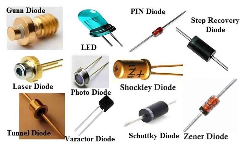
Diode fault checking
- Using Continuity Mode: When checking a diode with a multimeter set to continuity mode, the diode should allow current to pass in one direction, causing the multimeter to beep. This indicates that the diode is conducting in the forward direction. In the reverse direction, the diode should block current, and the multimeter will not beep. This behavior confirms that the diode is functioning properly.
- If Continuity is Detected in Both Directions: If the diode beeps in both directions during the continuity test, it may be faulty. To verify this, carefully desolder and remove the diode from the PCB. Test the diode again outside the circuit. If it still beeps in both directions, the diode is defective and should be replaced.
This method ensures proper identification of a faulty diode.
IC – Integrated Circuit
MOV
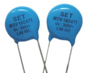
Metal Oxide Varistor (MOV)
An MOV (Metal Oxide Varistor) is a type of voltage-dependent resistor used to protect electronic circuits from high-voltage transients, such as surges or spikes. MOVs are commonly found in surge protectors and devices designed to safeguard sensitive electronics from voltage fluctuations.
MOV correct Connection
Construction
- Core Material: The core of an MOV is composed of a mixture of metal oxides, primarily zinc oxide, along with small amounts of other metal oxides like bismuth, manganese, or cobalt.
- Electrodes: The metal oxide material is sandwiched between two metal plates, which act as electrodes.
- Encapsulation: The entire assembly is coated with an epoxy or ceramic material for protection and insulation.
Working Principle
- MOVs act as nonlinear resistors. Under normal operating voltages, the MOV presents a high resistance, allowing little or no current to flow through.
- When a voltage spike or surge occurs, the MOV’s resistance dramatically decreases, allowing current to flow through it and bypass the sensitive electronic components. This clamps the voltage to a safe level, protecting the circuit.
- Once the surge is over, the MOV returns to its high-resistance state.
Key Parameters
- Clamping Voltage: The voltage at which the MOV starts to conduct and clamp the surge. It should be higher than the normal operating voltage of the circuit but low enough to protect sensitive components.
- Maximum Energy Rating: The amount of energy the MOV can absorb during a surge event, measured in joules. Higher energy ratings indicate the MOV can handle larger surges.
- Response Time: MOVs are very fast and can respond to voltage spikes within nanoseconds.
- Capacitance: MOVs have some inherent capacitance, which can affect high-frequency circuits.
Applications
- Surge Protection Devices (SPD): MOVs are commonly used in power strips, surge protectors, and circuit boards to protect against lightning strikes or power surges.
- Power Supplies: MOVs protect AC mains circuits from overvoltage conditions.
- Telecommunication Systems: Used to protect sensitive communication equipment from voltage spikes.
- Electronic Appliances: MOVs are installed in appliances like refrigerators, washing machines, and other household devices to prevent damage from sudden voltage spikes.
Advantages
- Fast Response Time: MOVs respond almost instantaneously to voltage spikes, providing quick protection to the circuit.
- Cost-Effective: MOVs are relatively inexpensive and easy to integrate into circuits.
- High Surge Capability: They can absorb large amounts of energy without damage, making them ideal for protecting against high-energy transients.
Disadvantages
- Limited Lifespan: Each time an MOV absorbs a surge, it degrades slightly. Over time, its effectiveness reduces, and it may eventually fail.
- Thermal Runaway: If an MOV repeatedly experiences surges or is exposed to a prolonged overvoltage, it may overheat and potentially fail, sometimes leading to fire hazards if not properly designed.
Fault Detection in MOVs
- Physical Inspection: Look for signs of discoloration, cracking, or burning. An MOV that has absorbed too many surges may show physical damage.
- Testing: Use a multimeter to check for continuity. A failed MOV might show as a short circuit or continous beep in Multimeter continuity mode (low resistance) if it’s been exposed to a severe overvoltage event.
- Performance Degradation: If the device or circuit protected by the MOV no longer responds to surges, it might be due to the MOV reaching the end of its life.
How MOV Protects Electronics
- Under Normal Conditions: The MOV remains inactive, allowing the circuit to function normally.
- During a Surge Event: The MOV’s resistance drops, diverting the surge current away from sensitive components.
- Post-Surge: The MOV returns to its high-resistance state once the surge has passed.
Conclusion
MOVs are crucial components in surge protection circuits, offering fast response and effective voltage clamping to prevent damage to sensitive electronics. While they have limitations like degradation over time, their ability to protect against transient voltage surges makes them a valuable and cost-effective solution.
L – Inductor
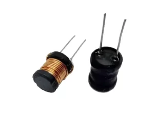
In a PCB (Printed Circuit Board), the designation L1 typically refers to an inductor. Inductors are passive components that store energy in the form of a magnetic field when current flows through them. They are commonly used in power supplies, filters, and other circuits where electromagnetic properties are crucial.
- L1 indicates the first inductor in the circuit.
- Inductors may appear as coils, toroidal shapes, or surface-mounted components.
How to Detect a Fault in an Inductor (L1)?
Detecting a fault in an inductor (L1) can involve a few key steps:
1. Visual Inspection
- Look for physical damage, such as burn marks, discoloration, or broken wires.
- Check for loose connections or solder joints on the PCB.
2. Testing for Continuity
- Set the multimeter to continuity mode.
- Place the probes on both ends of the inductor (L1).
- A beep sound indicates that the inductor is not open (there’s a path for current). If there’s no beep, the inductor might be open (broken) and needs replacement.
3. Measuring Inductance
- Set the multimeter to inductance measurement mode (if available) or use an LCR meter.
- Measure the inductance and compare it to the inductor’s rated value (which can be found in the circuit diagram or component markings).
- If the inductance value is too high or too low, the inductor might be faulty.
4. Checking Resistance
- Set the multimeter to resistance mode (ohms).
- Measure the resistance across L1. A very high resistance (close to infinity) could indicate an open circuit (broken inductor).
- A very low resistance (close to 0 ohms) may indicate a short in the inductor, which is also a fault.
5. Testing in Circuit
- If L1 is part of a larger circuit, you may need to isolate it from the circuit to get accurate measurements. Desolder one leg of the inductor and then test it with the multimeter.
Common Faults in Inductors (L1)
- Open Circuit: The wire inside the inductor is broken, causing no current flow.
- Short Circuit: The inductor may have shorted internally, reducing its inductance significantly.
- Physical Damage: External damage to the component, often due to overheating or high currents.
By following these steps, you can determine if L1 is functioning properly or if it needs replacement.
What is difference between Inductor coil and drum coil?
Yes, in the context of a PCB (Printed Circuit Board), a drum coil and an inductor are essentially the same in terms of their function, but they differ slightly in design and appearance.
Key Differences:
- Drum Coil:
- A drum coil is a specific type of inductor shaped like a drum with windings wrapped around a cylindrical core.
- It is commonly used in power supply circuits and filtering applications.
- Its design allows for higher current handling and better performance in power regulation.
- Inductor:
- An inductor is a more general term for a passive component that stores energy in a magnetic field when current flows through it.
- Inductors come in various forms, including drum coils, toroidal coils, chip inductors, and more.
- The specific type of inductor used depends on the application requirements such as size, inductance value, current rating, and frequency response.
In Summary:
- Drum coil is a type of inductor, and both serve the same purpose in a PCB: to store energy in a magnetic field, filter signals, or regulate current.
- They may look different, but they both perform the same fundamental electrical function.
So, while all drum coils are inductors, not all inductors are drum coils.
Octocoupuler

An optocoupler (also known as an optoisolator) is an electronic component that allows the transfer of electrical signals between two isolated circuits using light. It provides electrical isolation between its input and output, protecting sensitive components from high voltages or electrical noise.
How It Works:
An optocoupler consists of two main parts:
- Light-emitting diode (LED): On the input side, when an electrical signal is applied, the LED emits light.
- Photodetector (usually a phototransistor): On the output side, the photodetector receives the light from the LED and turns it back into an electrical signal.
Since the light is used to transfer the signal, there is no direct electrical connection between the input and output, which provides isolation.
Key Features:
- Electrical Isolation: The input and output are electrically independent, which is important for preventing electrical surges from damaging sensitive components.
- Signal Transfer: Optocouplers can pass digital signals, PWM signals, or other data while maintaining isolation.
Applications:
- Microcontroller Protection: Protects microcontrollers from high-voltage circuits.
- Switching Devices: Used to control high-power devices, like relays, without a direct connection to low-power circuits.
- Signal Isolation: Isolates noisy circuits, improving signal integrity in communication systems.
In summary, an optocoupler isolates two parts of a system electrically while allowing them to communicate through light.
Fault detection in octocoupler
Q – Transistor
R – Resistor
Fault Detection in Resistor
- Fuse resistance may beep during testing because they are of Low resistance.
- IF the resistor beeps and there are no reading in multimeter, then also the resistor is Shorted.
SMD Bridge rectifier
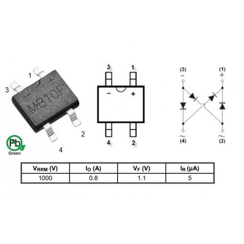
An SMD (Surface Mount Device) bridge rectifier is an electronic component that converts alternating current (AC) to direct current (DC) by using four diodes arranged in a bridge configuration. This component is widely used in power supply circuits for AC-to-DC conversion.
Key Features of SMD Bridge Rectifiers:
- Compact size: Surface-mount components are smaller than through-hole devices, making them ideal for modern, compact circuit boards.
- High efficiency: SMD bridge rectifiers have low forward voltage drops, which results in efficient conversion.
- Reliability: They are robust and can handle high voltages and currents in a wide range of temperatures.
- Easy PCB integration: SMD bridge rectifiers are easier to mount on PCB using automated processes.
Typical Applications:
- Power supply units (SMPS)
- AC adapters
- Chargers for electronics
- Industrial power controls
- Rectifying circuits for motors
Fault Detection in SMD Bridge Rectifiers
Fault detection in SMD bridge rectifiers is essential for maintaining the reliability and efficiency of power supply circuits. Common faults can include short circuits, open circuits, and diode failure. Here are methods to detect these issues:
1. Diode Testing (Using a Multimeter)
A basic and common method for detecting faults is to test each diode in the bridge rectifier. You can use the diode testing mode of a multimeter.
- Set the multimeter to Diode Test Mode.
- Place the positive (red) probe on the anode and the negative (black) probe on the cathode of each diode.
- A forward-biased diode will typically show a voltage drop between 0.5V to 0.7V. If it shows 0V or OL (over-limit), the diode might be shorted or open.
- Repeat this test for all four diodes in the bridge configuration.
Common Faults Detected:
- Open Diode: If no current flows in the forward direction (shows OL), the diode is open and faulty.
- Shorted Diode: If the diode shows 0V in both forward and reverse bias, it is shorted.
- Leakage: If the reverse-biased diode shows a voltage drop, it may be leaking current, indicating failure.
2. Thermal Inspection (Heat Buildup)
During operation, faulty components can generate excess heat. Using a thermal camera or infrared thermometer, inspect the SMD bridge rectifier for unusual heat levels. A damaged diode may produce higher temperatures due to increased current draw or failure in the rectification process.
Common Faults Detected:
- Overheating Diodes: A shorted diode will lead to excessive current passing through it, causing localized heating.
- Heat Dissipation Issues: Poor solder joints or component damage can also cause improper heat dissipation, leading to failure.
3. Visual Inspection (PCB Damage)
Inspect the SMD bridge rectifier and its soldering joints visually for any signs of physical damage such as:
- Cracked or burnt component bodies.
- Solder joint issues (e.g., cold joints, cracks, or oxidation).
- PCB traces near the rectifier that appear burnt or damaged, which could indicate a short circuit or excessive current.
Common Faults Detected:
- Burnt Components or PCB Traces: This indicates excessive heat due to short circuits or overvoltage conditions.
- Cold Solder Joints: Poor connections may result in intermittent failures, leading to faulty rectification.
4. In-circuit Testing
You can also perform in-circuit measurements under operational conditions by probing the input and output of the bridge rectifier.
- Measure the AC input voltage at the two input terminals.
- Measure the DC output voltage across the + and – terminals.
- Verify that the output DC voltage is correct according to the design specifications (typically Vout ≈ 0.9 * Vin AC RMS for a full-wave rectifier).
Common Faults Detected:
- No Output Voltage: Could indicate open diodes or improper rectification.
- Low Output Voltage: May indicate a partially shorted diode or excessive load drawing current.
5. Oscilloscope Testing
Using an oscilloscope, you can observe the waveform of the input and output signals of the bridge rectifier.
- Connect the oscilloscope probes to the AC input and observe the waveform.
- Probe the DC output and check for a smooth DC waveform.
Common Faults Detected:
- Ripple in DC Output: Excessive ripple indicates improper rectification, often due to diode failure or filter capacitor issues.
- Distorted Input Waveform: Could indicate a shorted diode or malfunctioning component in the circuit affecting input power
Common Causes of Faults in SMD Bridge Rectifiers
- Excessive Voltage or Current: Operating above the rated voltage or current capacity of the rectifier can cause the diodes to fail.
- Reverse Voltage Spikes: Sudden voltage spikes in reverse bias can cause damage to the diodes, leading to breakdown.
- Overheating: If the rectifier lacks proper heat dissipation, excessive heat can cause thermal runaway and component failure.
- Soldering Issues: Improper solder joints can lead to poor electrical connections or intermittent failures.
- Aging Components: Over time, diodes may wear out due to thermal cycling and electrical stress.
T – Transformer
U – Integrated circuit
In a PCB (Printed Circuit Board), the designation “U” typically refers to an integrated circuit (IC) or microchip. The letter “U” is a standard reference designator used in schematics and PCB layouts to identify ICs, microcontrollers, or other types of chips.
Example:
- U1: The first integrated circuit on the board.
- U2: The second integrated circuit, and so on.
These components perform various functions such as processing, memory storage, or control in electronic circuits.